- 您现在的位置:买卖IC网 > Sheet目录1214 > EVAL-ADE7754EBZ (Analog Devices Inc)BOARD EVALAUTION FOR ADE7754
�� ��
��
��ADE7754�
�and� voltage� gain� registers.� See� the� Current� RMS� Calculation�
�and� Voltage� RMS� Calculation� sections.� Only� the� effect� of� the�
�apparent� power� gain� is� shown� on� Figure� 35.� The� minimum�
�output� range� is� given� when� the� apparent� power� gain� register�
�content� is� equal� to� 800h� and� the� maximum� range� is� given� by�
�writing� 7FFh� to� the� apparent� power� gain� register.� This� can� be�
�used� to� calibrate� the� apparent� power� (or� energy)� calculation�
�in� the� ADE7754� for� each� phase� and� the� total� apparent� energy.�
�See� the� Total� Apparent� Power� Calculation� section.�
�The� total� apparent� power� calculated� by� the� ADE7754� depends� on�
�the� configuration� of� the� VAMOD� bits� in� the� VAMode� register.�
�Each� term� of� the� formula� used� can� be� disabled� or� enabled� by� the�
�setting� VASEL� bits,� respectively,� to� Logic� 0� or� Logic� 1� in� the�
�VAMode� register.� The� different� configurations� are� described� in�
�Table� IV.�
�Table� IV.� Total� Apparent� Power� Calculation�
�APPARENT�
�VAMOD� VASEL0�
�VASEL1�
�VASEL2�
�POWER�
�13A929h�
�D1B71h�
�68DB9h�
�00000h�
�VOLTAGE� CHANNEL� AND�
�CURRENT� CHANNEL� 0.5V/GAIN�
�+� 150%� FS�
�+� 100%� FS�
�+� 50%� FS�
�AVAGAIN[11:0]�
�0d�
�1d�
�2d�
�V� ARMS� � I� ARMS�
�V� ARMS� � I� ARMS�
�V� ARMS� � I� ARMS�
�+� V� BRMS� � I� BRMS�
�+(V� ARMS� +� V� CRMS� )�
�/2� I� BRMS�
�+� V� ARMS� � I� BRMS�
�+� V� CRMS� � I� CRMS�
�+� V� CRMS� � I� CRMS�
�+� V� CRMS� � I� CRMS�
�F97247h�
�–� 50%� FS�
�F2E48Fh�
�EC56D7h�
�000h�
�7FFh� 800h�
�–� 100%� FS�
�–� 150%� FS�
�Note� that� V� ARMS� ,� V� BRMS� ,� V� CRMS� ,� I� ARMS� ,� I� BRMS� ,� and� I� CRMS� represent�
�the� voltage� and� current� channels� RMS� values� of� the� corresponding�
�registers.�
�Figure� 35.� Apparent� Power� Calculation� Output� Range�
�Apparent� Power� Offset� Calibration�
�For� example,� for� VAMOD� =� 1,� the� formula� used� to� process� the�
�apparent� power� is�
�Total� Apparent� Power� =� V� ARMS� � I� ARMS� � ?� 1� +�
�?�
�Each� rms� measurement� includes� an� offset� compensation� register�
�to� calibrate� and� eliminate� the� dc� component� in� the� rms� value.�
�See� the� Current� RMS� Calculation� and� Voltage� RMS� Calculation�
�?�
�?�
�AVAG� ?�
�2� 12� ?�
�� I� BRMS� � ?� 1� +�
�?�
�sections.� The� voltage� and� current� rms� values� are� then� multiplied�
�in� the� apparent� power� signal� processing.� Because� no� additional�
�offsets� are� created� in� the� multiplication� of� the� rms� values,� there�
�+�
�(� V� ARMS� +� V� CRMS� )�
�2�
�?�
�?�
�BVAG� ?�
�2� 12� ?�
�+� V� CRMS� CRMS� � ?� 1� +�
�� I�
�?�
�is� no� specific� offset� compensation� in� the� apparent� power� signal�
�processing.� The� offset� compensation� of� the� apparent� power�
�measurement� in� each� phase� is� done� by� calibrating� each� indi-�
�?�
�?�
�CVAG� ?�
�2� 12� ?�
�vidual� rms� measurement.�
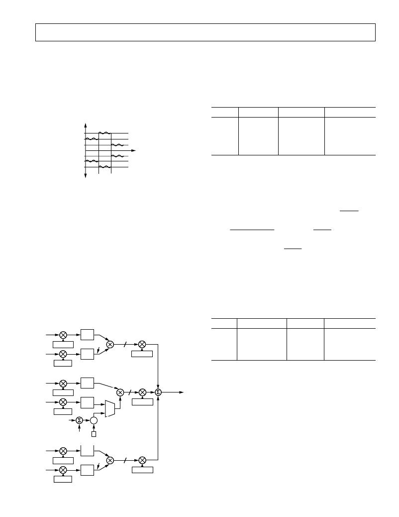
�TOTAL� APPARENT� POWER� CALCULATION�
�The� sum� of� the� apparent� powers� coming� from� each� phase� gives�
�the� total� apparent� power� consumption.� Different� combinations�
�of� the� three� phases� can� be� selected� in� the� sum� by� setting� Bits� 7�
�and� 6� of� the� VAMode� register� (mnemonic� VAMOD[1:0]).� Figure� 36�
�demonstrates� the� calculation� of� the� total� apparent� power.�
�The� polyphase� meter� configuration� determines� which� formula�
�should� be� used� to� calculate� the� apparent� energy.� The� American�
�ANSI� C12.10� standard� defines� the� different� configurations� of�
�the� meter.� Table� V� describes� which� mode� should� be� chosen� for�
�different� configurations.�
�Table� V.� Meter� Form� Configuration�
�PHASE� A�
�ANSI�
�Meter� Form�
�VAMOD�
�VASEL�
�I� A�
�V� A�
�AAPGAIN�
�RMS�
�RMS�
�V� ARMS�
�24�
�AVAGAIN�
�5S/13S�
�6S/14S�
�8S/15S�
�9S/16S�
�3-wire� Delta�
�4-wire� Wye�
�4-wire� Delta�
�4-wire� Wye�
�0�
�1�
�2�
�0�
�3� or� 5� or� 6�
�7�
�7�
�7�
�AVGAIN�
�PHASE� B�
�Different� gain� calibration� parameters� are� offered� in� the� ADE7754�
�to� cover� the� calibration� of� the� meter� in� different� configurations.�
�I� B�
�V� B�
�BAPGAIN�
�RMS�
�RMS�
�24�
�BVAGAIN�
�TOTAL� APPARENT�
�POWER� SIGNAL�
�The� APGAIN,� VGAIN,� and� VAGAIN� registers� have� different�
�purposes� in� the� signal� processing� of� the� ADE7754.� APGAIN�
�registers� affect� the� apparent� power� calculation� but� should� be�
�used� only� for� active� power� calibration.� VAGAIN� registers� are�
�BVGAIN�
�used� to� calibrate� the� apparent� power� calculation.� VGAIN� regis-�
�V� ARMS�
�+�
�+�
�%�
�ters� have� the� same� effect� as� VAGAIN� registers� when� VAMOD� =�
�0� or� 2.� They� should� be� left� at� their� default� value� in� these� modes.�
�PHASE� C�
�V� CRMS�
�2�
�VGAIN� registers� should� be� used� to� compensate� gain� mismatches�
�between� channels� in� VAMOD� =� 1.�
�I� C�
�V� C�
�CAPGAIN�
�RMS�
�RMS�
�V� CRMS�
�24�
�CVAGAIN�
�As� mentioned� previously,� the� offset� compensation� of� the� phase�
�apparent� power� calculation� is� done� in� each� individual� rms� mea-�
�surement� signal� processing.� See� the� Apparent� Power� Offset�
�Calibration� section.�
�CVGAIN�
�Figure� 36.� Total� Apparent� Power� Calculation�
�REV.� 0�
�–25� –�
�发布紧急采购,3分钟左右您将得到回复。
相关PDF资料
EVAL-ADE7755ZEB
BOARD EVALUATION FOR AD7755
EVAL-ADE7758ZEB
BOARD EVAL FOR AD7758
EVAL-ADE7759EBZ
BOARD EVALUATION FOR ADE7759
EVAL-ADE7762EBZ
BOARD EVALUATION FOR ADE7762
EVAL-ADE7763ZEB
BOARD EVALUATION FOR ADE7763
EVAL-ADE7816EBZ
BOARD EVALUATION FOR ADE7816
EVAL-ADE7878EBZ
BOARD EVAL FOR ADE7878
EVAL-ADE7880EBZ
BOARD EVAL FOR ADE7880
相关代理商/技术参数
EVAL-ADE7755EB
制造商:Analog Devices 功能描述:EVAL BOARD ENERGY METERINGW/PULSE OUTPUT - Bulk
EVAL-ADE7755EBZ
制造商:AD 制造商全称:Analog Devices 功能描述:Energy Metering IC with Pulse Output
EVAL-ADE7755EBZ1
制造商:AD 制造商全称:Analog Devices 功能描述:Energy Metering IC with Pulse Output
EVAL-ADE7755ZEB
功能描述:BOARD EVALUATION FOR AD7755 RoHS:是 类别:编程器,开发系统 >> 评估演示板和套件 系列:- 标准包装:1 系列:- 主要目的:电信,线路接口单元(LIU) 嵌入式:- 已用 IC / 零件:IDT82V2081 主要属性:T1/J1/E1 LIU 次要属性:- 已供物品:板,电源,线缆,CD 其它名称:82EBV2081
EVAL-ADE7756EB
制造商:Analog Devices 功能描述:EVAL BD DOCUMENTATION ADE7756 ENERGY METERING IC - Bulk 制造商:Rochester Electronics LLC 功能描述:
EVAL-ADE7757AEBZ
制造商:Analog Devices 功能描述:EVALUATION BOARDS - Bulk
EVAL-ADE7757EB
制造商:Analog Devices 功能描述:EVAL BOARD ENERGY METERINGW/PULSE OUTPUT - Bulk
EVAL-ADE7758ZEB
功能描述:BOARD EVAL FOR AD7758 RoHS:是 类别:编程器,开发系统 >> 评估演示板和套件 系列:* 标准包装:1 系列:PSoC® 主要目的:电源管理,热管理 嵌入式:- 已用 IC / 零件:- 主要属性:- 次要属性:- 已供物品:板,CD,电源